
Deburring Machine Configuration Comparison
Choosing a deburring machine involves more than selecting its working width. The processing units—and the order in which a workpiece passes through them—determine which finishing tasks the configuration is intended to perform.
Lasvio’s configuration range combines hammer-disc, abrasive belt, rotary brush, and surface finishing units. This guide explains the combinations in the configuration list and how to compare them against your parts.
What Do H, B, R and P Mean?
| Code | Processing unit | Main role |
|---|---|---|
| H | Slag removal hammer-disc unit | Heavy and hard slag removal |
| B | Abrasive belt unit | Burr removal and surface grinding; slag and oxide-layer removal where suitable |
| R | Rotary brush unit | Edge rounding |
| P | Surface finishing roller | Straight-line surface brushing |
A repeated letter indicates an additional unit of that type. The letter order describes the processing sequence for the listed configurations. A brush unit is an assembly; the code does not describe the number of individual brushes visible inside the machine.
Compare the Configurations
| Configuration | Processing units | Main processing tasks |
|---|---|---|
| HB / HBB | One hammer-disc unit plus one or two abrasive belt units | Heavy and hard slag removal |
| R / RR | One or two rotary brush units | Edge rounding |
| BB | Two abrasive belt units | Slag, burr and oxide-layer removal |
| BR | One abrasive belt unit followed by one rotary brush unit | Removal followed by edge rounding |
| BRB / BBR | Two abrasive belt units and one rotary brush unit, in different sequences | Removal and edge rounding with an additional belt stage |
| BRP | One abrasive belt unit, one rotary brush unit and one surface finishing roller | Removal, edge rounding and straight-line surface brushing |
| BRBP / BBRP | Two abrasive belt units, one rotary brush unit and one surface finishing roller | Four-stage removal, edge rounding and straight-line surface brushing |
HB and HBB: Start with Heavy Slag Removal
In these illustrations, workpieces enter from the right and travel left through the processing units.
HBB
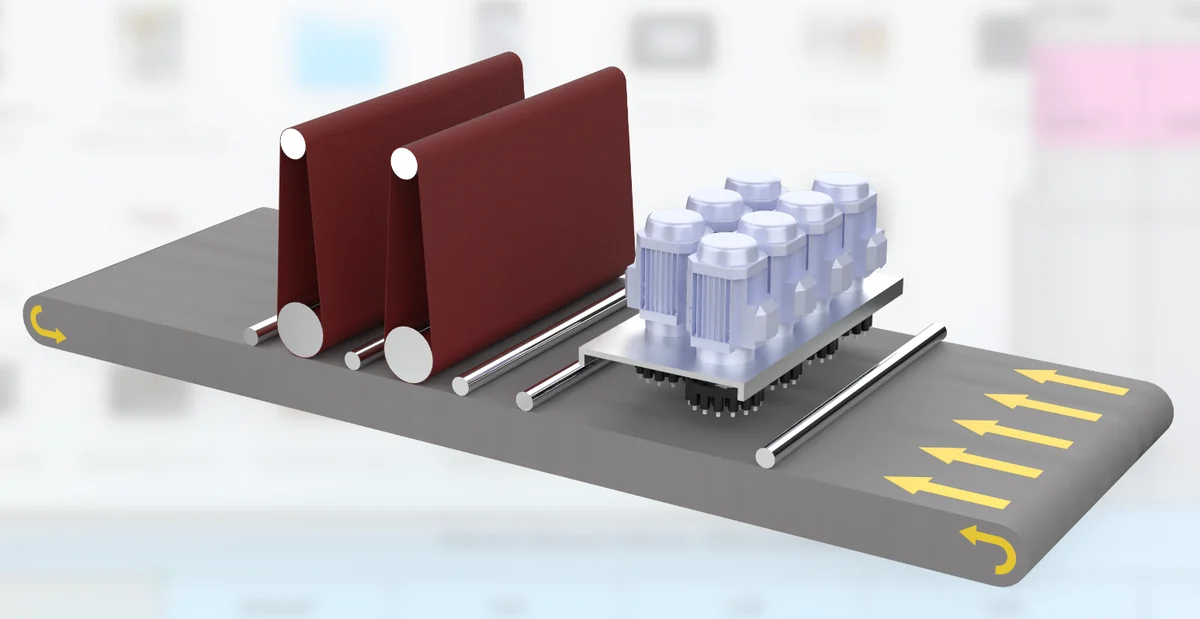
HB and HBB place a hammer-disc stage before abrasive belt processing. They are the configurations identified in the list for heavy and hard slag removal.
HB includes one abrasive belt stage after the hammer-disc unit; HBB includes two. The appropriate choice depends on the remaining work after the initial slag-removal stage.
When submitting samples, include parts showing the range of slag conditions found in daily production. Confirm whether the finished parts also need a controlled edge radius or a decorative surface finish; do not assume those requirements are covered by the slag-removal configuration alone.
Decision guide: Choose this route when hard thermal-cut slag is the bottleneck. See the Slag & Dross Removal solution for BB / HB / HBB model selection.
R, RR, BB and BR: Match the Units to the Task
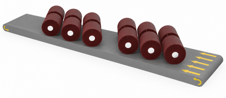
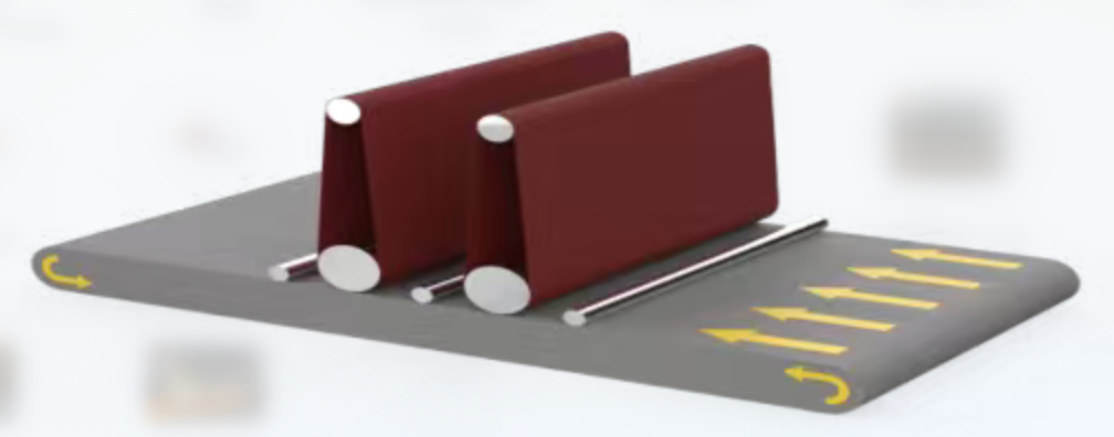
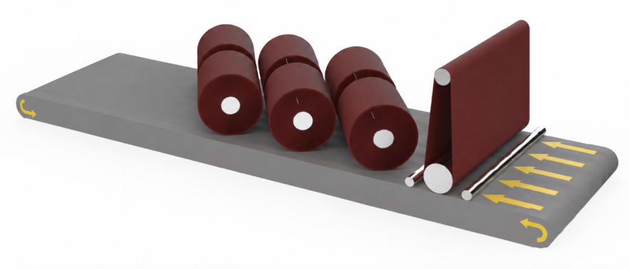
In these illustrations, workpieces enter from the right and travel left through the processing units.
RR
BB
BR
R and RR focus on edge rounding, with one or two rotary brush units. If raised burrs or substantial slag must also be removed, assess whether preceding removal stages are needed.
BB provides two abrasive belt units for removal and surface grinding tasks. It does not include a rotary brush unit or a separate P finishing roller.
BR combines an abrasive belt with a rotary brush, so removal is followed by edge rounding. It offers a different process sequence from a belt-only configuration.
The selection should follow the incoming part condition and acceptance requirement, rather than simply the number of stations.
Decision guide: If the goal is safer handling and consistent radius, start with the Edge Rounding Only solution. If burr removal must happen before rounding, compare it with the Deburring & Edge Rounding solution.
BBR vs BRB: The Same Unit Count, a Different Sequence
In these illustrations, workpieces enter from the right and travel left through the processing units.
BBR
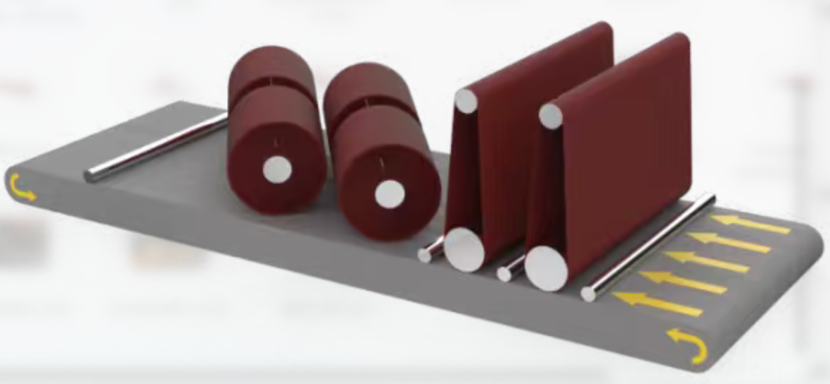
BRB
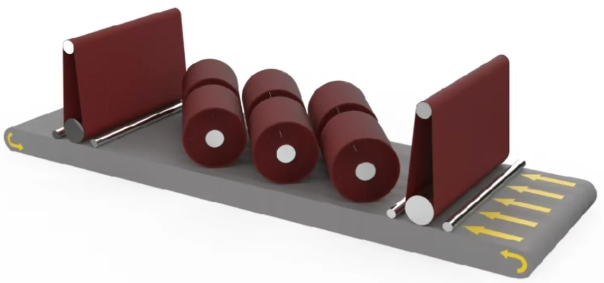
BBR: Abrasive Belt → Abrasive Belt → Rotary Brush
Two belt stages process the workpiece before the brush stage rounds the edges. This is a configuration to evaluate when additional removal work is needed before edge rounding.
BRB: Abrasive Belt → Rotary Brush → Abrasive Belt
The first belt performs removal, the brush rounds the edges, and the final belt refines the surface. This is a configuration to evaluate when the surface after brushing needs further belt treatment.
The source configuration notes identify BBR with a greater emphasis on removal before rounding, and BRB with final surface refinement. Neither sequence guarantees a better result for every part. Confirm the final edge and surface together using the actual material, abrasives and settings.
Decision guide: Use BR / BBR / BRB when the part needs both burr removal and edge rounding. Review the Deburring & Edge Rounding solution and send sample parts to confirm the sequence.
BRP, BRBP and BBRP: Add a Dedicated Surface Finishing Stage
In these illustrations, workpieces enter from the right and travel left through the processing units.
BRP
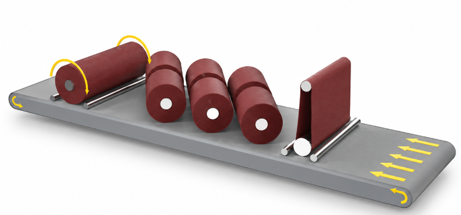
BRBP
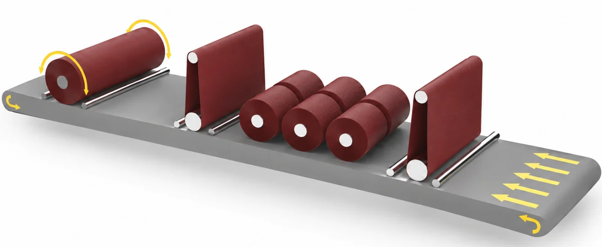
BBRP
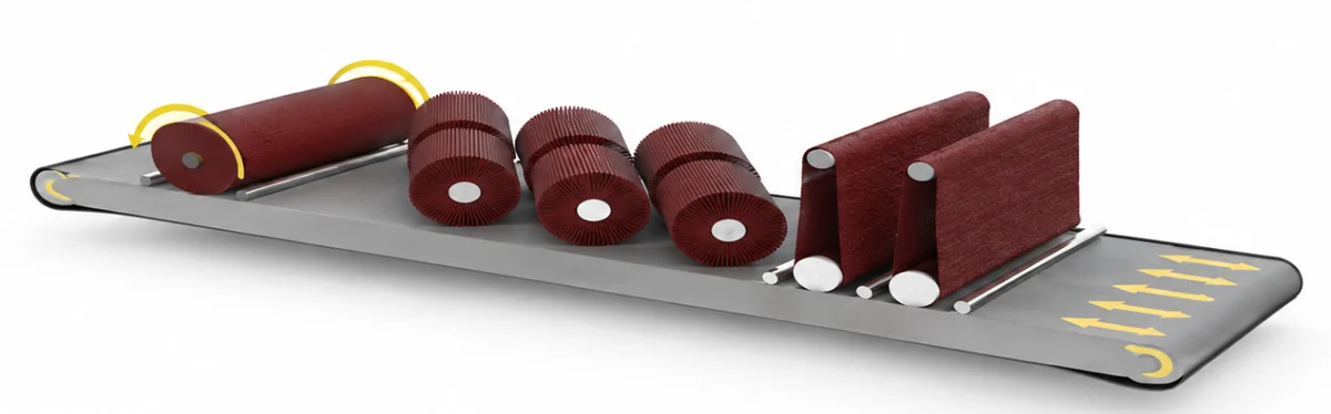
The P unit is a surface finishing roller for straight-line brushing.
BRP combines belt processing, rotary brushing and surface finishing in three stages. BRBP and BBRP each contain four stages: two abrasive belts, one rotary brush unit and one surface finishing roller.
Their sequences differ:
- BRBP: Abrasive belt → Rotary brush → Abrasive belt → Surface finishing roller.
- BBRP: Abrasive belt → Abrasive belt → Rotary brush → Surface finishing roller.
A four-stage configuration adds a belt stage compared with BRP. Its value depends on whether that stage performs useful work for your parts. Specify the required surface appearance and edge quality so both can be assessed during testing.
Decision guide: Choose BRP / BBRP / BRBP when visible surface brushing is part of the requirement. See the Complete Finishing solution for surface finishing sequences.
Working Width, Workpiece Holding and Dust Collection
All machine configurations are available in working widths of 800mm, 1000mm, 1300mm & 1600mm. Width alone does not establish minimum part size, thickness range or throughput.
Magnetic or vacuum workpiece holding is listed across the range. The appropriate arrangement must be matched to the material and part geometry.
The list identifies a wet dust collector as optional equipment. This describes an equipment option, not permission to operate without suitable dust control. Confirm the required extraction arrangement for the material and process as part of the machine specification.
Decision guide: If the workflow needs one-side loading, repeat passes or reduced walking, review the U Turn Return Conveyor solution with the selected machine width.
Compare Configurations with Your Own Samples
Provide Lasvio with the material, thickness range, part dimensions, cutting process, burr or slag condition, target edge radius and surface requirement.
For a useful comparison, evaluate the same representative parts against the same acceptance criteria. Record the number of passes, remaining manual work, surface appearance, edge quality and processing time.
Select the configuration that meets the production requirement with an appropriate sequence of operations. Additional units should have a clear purpose.